II. Hardware Connection & Installation Manual
* * *
> **This document is a manual for hardware connection and installation of the SafeMesh system**
> **Adaptation system version**: V1.0.0
> **Document version**: V1.0
> **Release date**: January 1, 2026
> **Published by**: EFFORT
* * *
# Document
revisionRevision recordsRecords
| Version number | Revision date | Summary of revisions | Reviser | Reviewer |
| --- | --- | --- | --- | --- |
| V1.0 | 2026-1-1 | Initial release | Shyne | Shyne |
* * *
# 1\. Preamble
## 1.1 Document Objectives
* Provides physical installation standards for gateways and terminal devices
* Guide the completion of the inter-equipment connection and preliminary testing
## 1.2 Target
audienceAudience
* Field engineer
## 1.3 Document Scope
* Hardware installation steps
* Initial testing steps for hardware connections
## 1.4 Related Documentation
* Prerequisite Document: System Overview and Installation Guide
* Parallel Documentation: Software Installation and Configuration Manual
* Related documents: "Gateway Manual" and "Terminal Product Manual"
## 1.5 Conventions and Symbols
* ⚠️ High pressure warning
* 🔧 Professional tools are required
* ℹ️ Tip information
# 2\. Preparation
beforeBefore deploymentDeployment
## 2.1 Environmental
verificationVerification checklistChecklist
| Inspection items | Standard requirements: | Verification tool |
| --- | --- | --- |
| Temperature range | \-20℃ ~ 55℃ | Thermometer |
| Humidity range | Dry | Hygrometer |
| Power stability | 220V±10% | Multimeter |
| Installation space | ≥ 60x60cm (Gateway) | tape measure |
## 2.2 Hardware Component List
| Component type | model | quantity |
| --- | --- | --- |
| Gateways | EIC-GW01-IOT/ZB | Some |
| router | Customers prepare their own | 1 |
| switches | Customers prepare their own | Some |
| ZigBee power supply | All ZigBee capable power supply models | Some |
## 2.3 Tool
kitKit preparationPreparation
* Phillips screwdriver (4mm head diameter)
# 3\. Hardware
installationInstallation standardsStandards
## 3.1 Deploy the
topologyTopology mapMap
[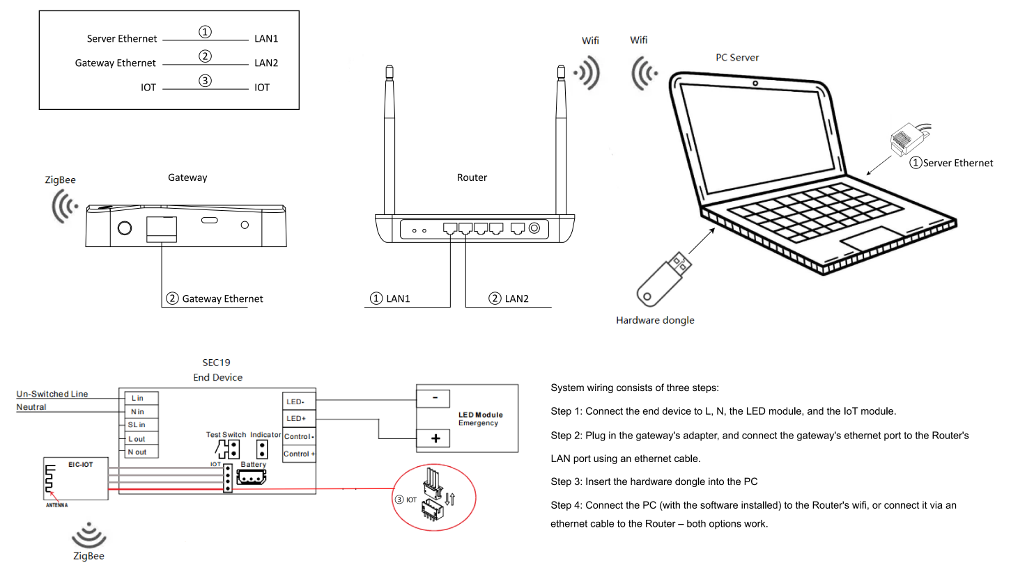](http://13.222.61.26:6875/uploads/images/gallery/2026-03/gwr5bus3zovh7wx1mfmcn4prnzb1.png)
## 3.2 Port Connection Specifications
| Equipment | ports | cables | Cable number |
| --- | --- | --- | --- |
| server | Server Ethernet | T568B <100m | (1) |
| Gateways | Gateway Ethernet | T568B <100m | (2) |
| router | LAN1 | T568B <100m | (1) |
| router | LAN2 | T568B <100m | (2) |
| terminal | IOT | 4P-Module cable | (3) |
| module | IOT | 4P-Module cable | (3) |
ℹ️ The server can choose to connect to the network using a network cable or to connect to the network using WIFI, and if WIFI is selected, no cable (1) is required
## 3.3 Power Wiring Specifications
| Equipment | Enter the parameters | interface | cables |
| --- | --- | --- | --- |
| Gateways | 5V-2A | Type-C | Type-C |
| terminal | 220VAC⚠️ | Power Input Terminal Block | AC Power Cable |
## 3.4 Gateway Installation Specifications
### 3.4.1 Number of Gateways:
* Specification: At least one gateway must be deployed independently for each physical floor. Sharing the gateway across floors is prohibited.
* Rationale: The floor structure (thickness, rebar content) causes significant attenuation of wireless signals (e.g., Zigbee), resulting in cross-layer communication: significantly weakened signal strength, unstable data transmission (errors, high latency), and even communication interruptions.
### 3.4.2 Gateway Location:
* Specification: Try to install the gateway in the geographic center of the floor.
* Basis: The Zigbee gateway signal is approximately spherical propagation. Centrally located deployment maximizes single-layer coverage uniformity, significantly reducing coverage dead zones and improving network reliability.
### 3.4.3 Gateway Capacity:
* Specification: A single gateway can carry up to 80 devices.
* Implementation requirements:
1. If the number of single-layer devices > 80, an additional gateway is required.
2. When deploying ≥ two gateways on the same floor, it must have the power supply control capability of the floor partition to ensure that the equipment can be powered on in batches and introduced into the system in stages.
### 3.4.4 Gateway Installation Method:
* Specification: It is forbidden to place it directly on the ground, and you should choose wall mounting 🔧 and desktop placement (placed on a ≥40cm countertop above the ground)
* Rationale: Harmful signal reflection will be generated on the ground, which will significantly reduce the effective communication distance of the wireless.
### 3.4.5 Gateway Installation Environment:
* Specification: It is strictly forbidden to install the gateway in a metal enclosed space or container.
* Basis: Metal has a strong shielding effect on wireless signals, which seriously reduces the communication distance and reliability.
## 3.5 Terminal
installationInstallation specificationsSpecifications
### 3.5.1 Terminal to Terminal Spacing:
* Specification: The maximum spacing between end devices should be < 30 meters.
* Basis: Ensure stable relay communication between nodes in a multi-hop network.
### 3.5.2 Terminal and Gateway Spacing:
* Specification: Each device group must have at least one endpoint with a distance of < 30 meters from the gateway.
* Rationale: The terminal will act as the first hop routing node to provide relay services to other devices in the same group (possibly > 30 meters apart) to ensure that all devices can communicate with the gateway.
### 3.5.3 Terminal
installationInstallation environmentEnvironment
* Specification: It is strictly forbidden to install terminal equipment in metal enclosed spaces or containers.
* Basis: Metal has a strong shielding effect on wireless signals, which seriously reduces the communication distance and reliability.
# 4\. How to
addAdd the
terminalTerminal to the
specifiedSpecified gatewayGateway
## 4.1 Background
descriptionDescription
In a multi-gateway deployment environment (such as the Industrial Internet of Things scenario), it is necessary to strictly control the binding relationship between the end device and the designated gateway (Coordinator). If all devices are powered on at the same time, the endpoint may join the non-target gateway for the following reasons:
* RSSI priority principle: The terminal defaults to the gateway with the strongest signal
* Beacon Frame Contention: Beacon frames broadcast by the gateway collide in the channel
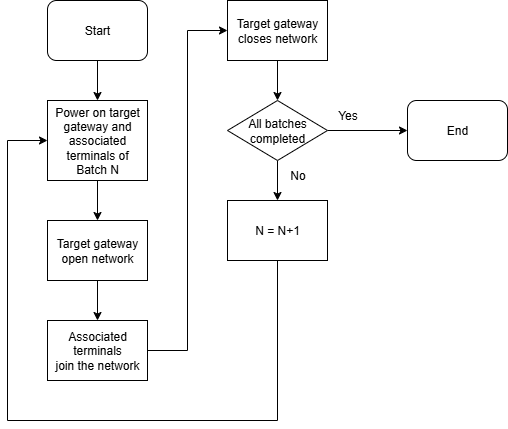
## 4.2 Technical
solutionsSolutions
Directional binding through physical isolation:
1. Power-on control in batches
2. Power only the batch 1 destination gateway and its associated endpoints
3. The target gateway opens the network to search for the associated endpoints
4. The destination gateway shuts down the network
5. Repeat operations on the batch 2 destination gateway and its associated endpoints
6. Cycle operation until the entire system is connected to the network
## 4.3 Flow
chartChart descriptionDescription
# 5\. Power-
onOn and
testTest processProcess
## 5.1 Power Boot Sequence
1. The router and switch devices are powered on
2. The end device under Gateway 1 is powered on
3. Wait 10 seconds
4. Gateway 1 is powered on
5. The server is powered on
## 5.2 Status
indicatorIndicator diagnosticsDiagnostics
| Equipment | Indicator status | Device status |
| --- | --- | --- |
| Gateways | Green is solid | Establish communication with the server |
| Gateways | Red is always on | No communication with the server is established |
| Gateways | Flashing red | Battery failure |
| terminal | Flashing green | The terminal is not networked |
| terminal | Green is solid | The terminal is networked |
## 5.3 Connectivity Testing
### 5.3.1 Network
connectivityConnectivity
* Test method: After the gateway is powered on for the first time, observe the status of the gateway indicator, if it is solid green, it means that the gateway has established communication with the server and is working normally. If it is solid red, it means that the gateway has not established communication with the server and is working abnormally.
* Test steps
1. Observe the status of the gateway indicator
2. If it is solid green, it means that it is working normally, and if it is solid red, check whether the wiring and server start the service normally
### 5.3.2 Is the
terminalTerminal workingWorking properly?Properly?
* Test method: After the terminal is powered on for the first time, observe the status of the terminal indicator, if it flashes green, it means that the terminal is not connected to the network and is working normally. If it is solid green, it means that the terminal is connected to the network or the module is not plugged in, and the operation is abnormal
* Test steps:
1. Observe the status of the terminal indicator.
2. If it flashes green, it means that it is working normally. If the module has confirmed the connection, you can reset the terminal by pressing and holding the test button for 10 seconds or switching the mains power off-on 3 times in a row within 20 seconds, and observe the terminal indicator status again after resetting.
### 5.3.3 ZigBee Network Connectivity
* Test method: After the gateway and terminal are powered on and working normally, start searching for devices through the server control gateway, and observe the status of the terminal indicator light. If the terminal keeps flashing green, it is working abnormally.
* Test steps:
1. Start searching for devices through the server-side control gateway.
2. Observe the status of the terminal indicator.
3. If it changes from flashing green to solid green, it means that the network access is successful. If the green flash is maintained and the network cannot be accessed, the terminal installation specification should be checked to see if the distance meets the requirements.
## 5.4 Repeat the
aboveAbove operationsOperations
As mentioned in 5.1, only the terminal devices under Gateway 1 and Gateway 1 are powered on at a time, and search and connectivity tests are conducted, and after the test is completed, continue to repeat the operation to power on the terminal devices under Gateway 2 and Gateway 2, and conduct search and connectivity tests, and so on until all equipment tests are completed.
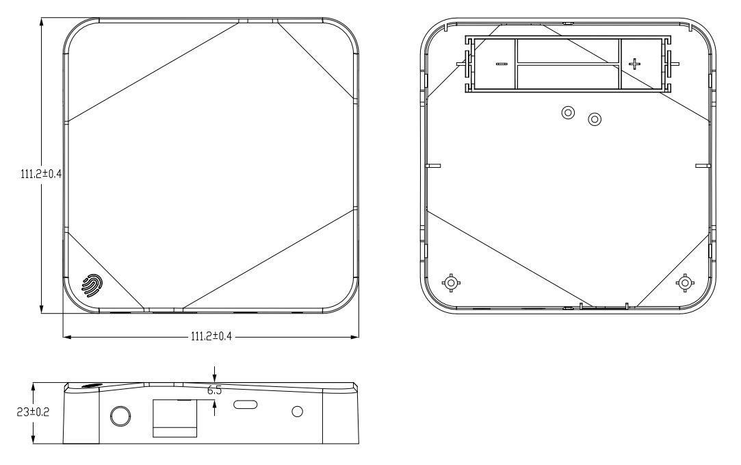
# 6\. Appendix
## 6.1 Gateway Mechanical Dimensions
## 6.2 Cable
specificationSpecification quickQuick checkCheck tableTable
| Signal type | Recommended cable model | Maximum transmission distance |
| --- | --- | --- |
| Ethernet | Cat6A T568B | 100m |
