
6.software operation user manual
Software operation manual
This document is the software user manual for the SafeLUX system
Adapted system version:V1.0.0
Document version:V1.0
Release Date:December 10, 2025
Publisher:EFFORT
Document modification record
| Version | Date | Modified content | Modifier |
|---|---|---|---|
| V1.0 | 20251210 | First creat | Mihcael |
1.Document overview
1.1 Overview
This document is the user manual for the built-in software of the SafeLUX system central control host (SLX-HT). By reading this document, you can understand the page composition, system usage, and permission management of the software system.
1.2 Target readers
- System administrators
- System operation and maintenance personnel
1.3 Scope of Document Content
- Software page introduction
- Introduction to System Permission Management
1.4 System usage requirements
- Power on the host
- Connect the screen through the HDMI interface of the host for operation
- Accessing the host's web page through a computer browser for operation
1.5 Term
Host
- SLX-HT
Master converter
Gateway devices with network communication
eg.SLX-GW-DL/C2
Sub converter
Gateway device with 485 communication
eg.SLX-GW/S-DL/C2
Node
- Emergency lighting fixtures or emergency drivers
Equipment
- Include “Master converter” “Sub converter” “Node”
2.Software page introduction
2.1 Menu list
Home menu list
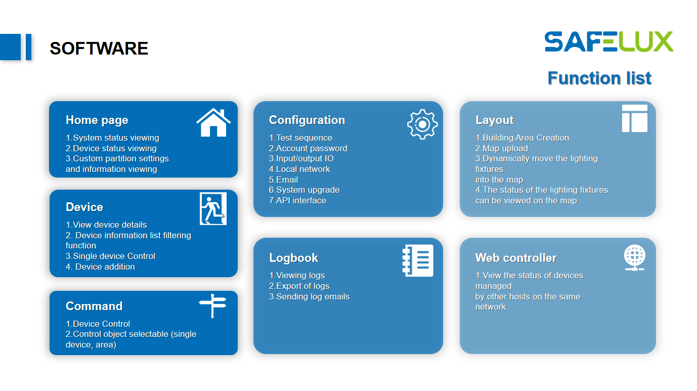
Function list
The SafeLUX system provides 7 management pages:
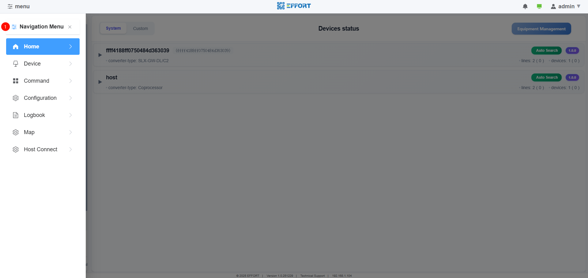
2.2 Home
2.2.1 Home page
Home
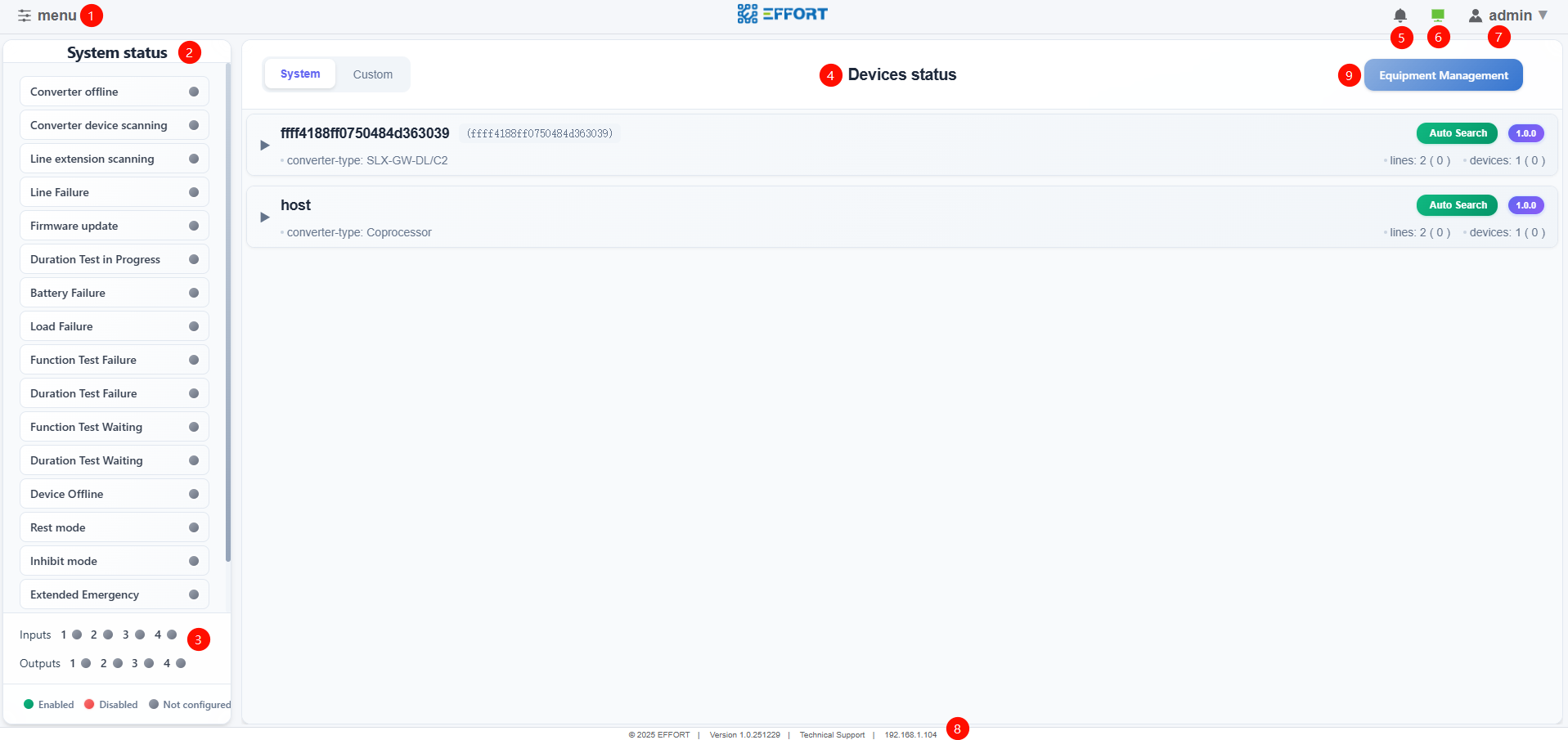
2.2.2 Equipment status
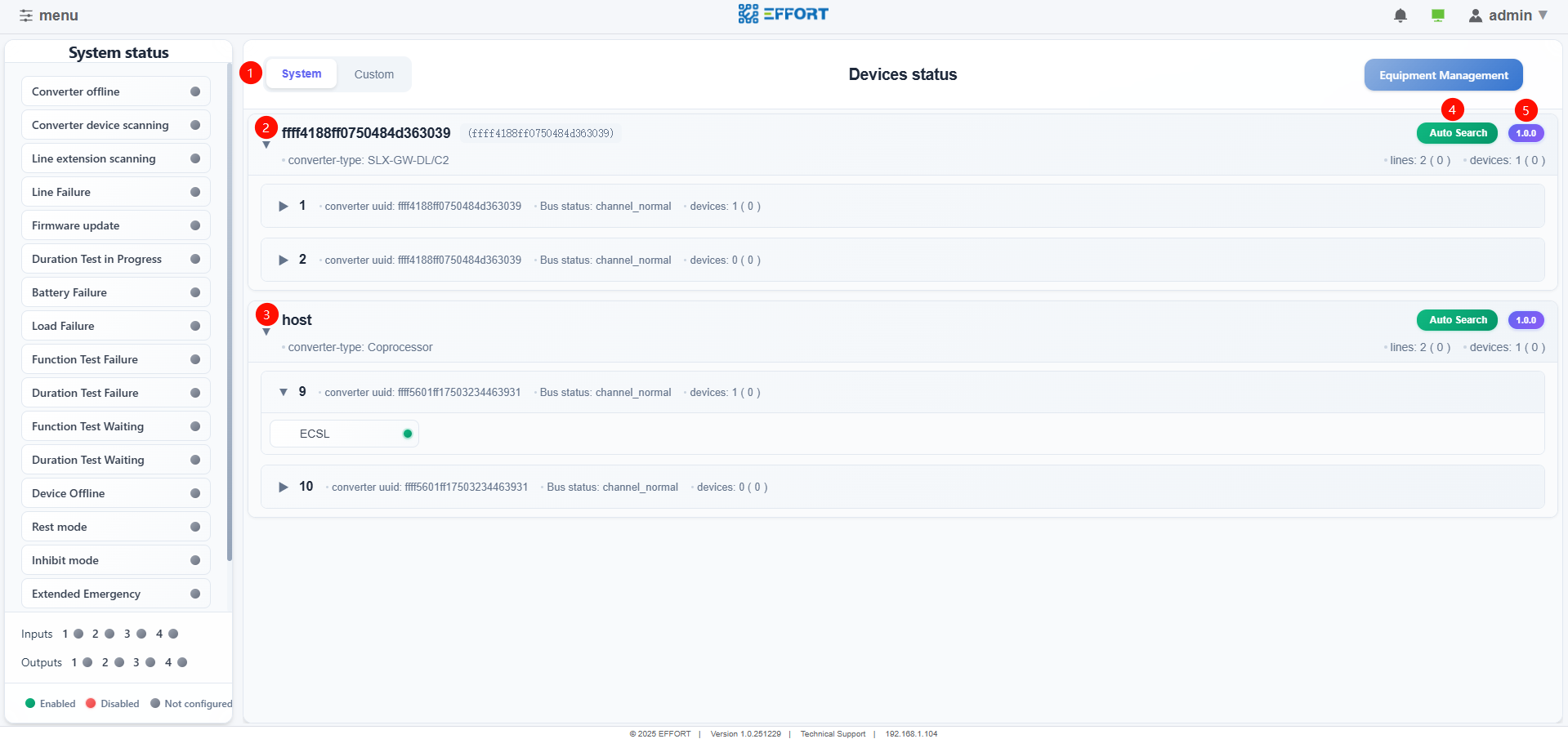
Equipment status
①Switch display mode
System:Default display layout based on physical links
Custom:User defined display layout
Master converter information
Master converter information added to the system
Information of sub converters extended through 485 for the master converter
Terminal device information
Information on the 485 bus of the host
Information of sub converters extended through 485 for the host
Terminal device information
Auto search
- Automatic Search Sub Converter and Terminal
Equipment software version
2.2.2 Equipment status(custom)
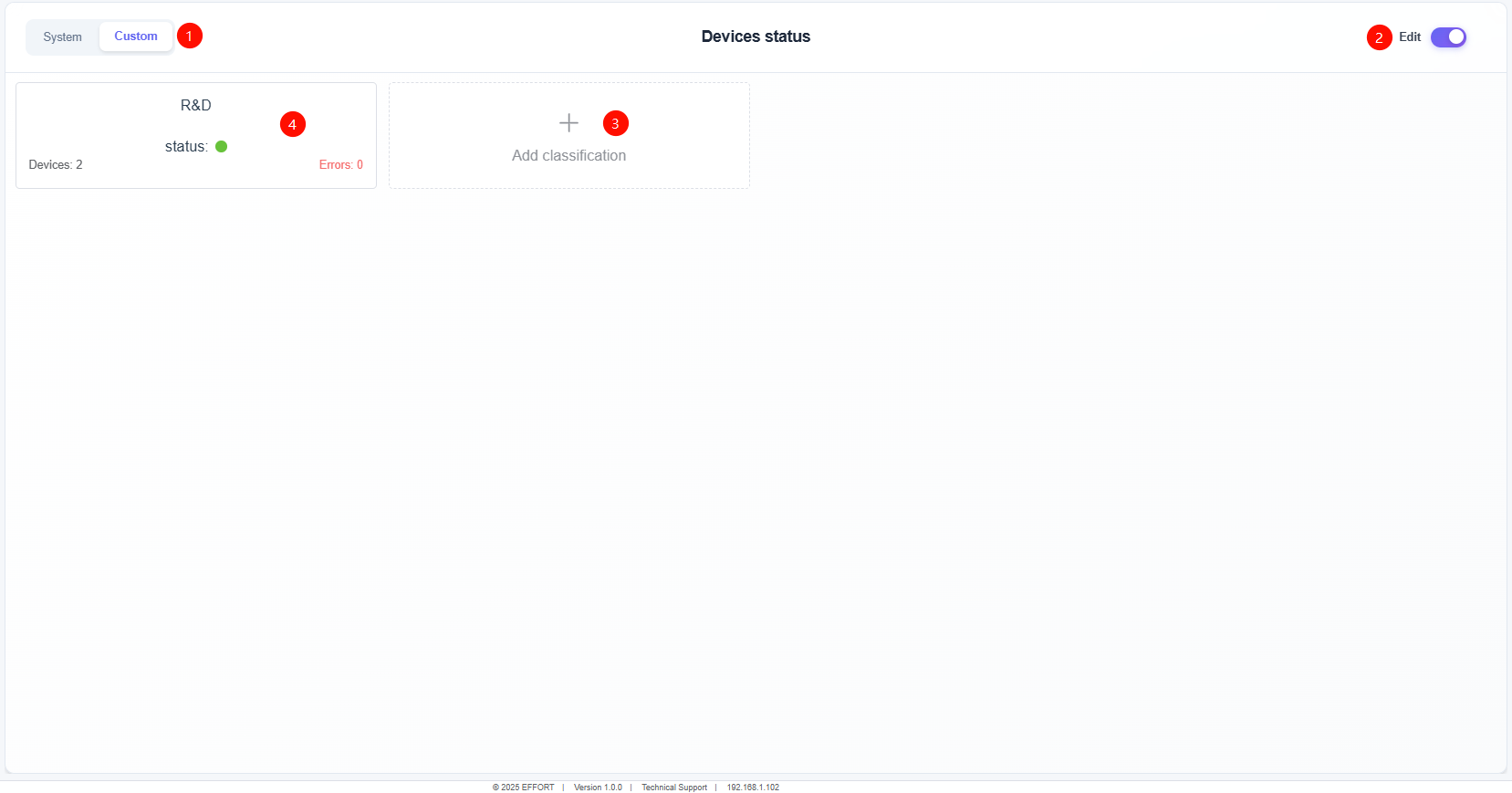
Equipment status(custom)
①Custom
Create custom areas that are not restricted by physical links
Any device can be added within the custom area
If there is a fault in the device within the custom area, the status will be displayed in red
The custom area with red status will be displayed at the top
Click on the area to directly jump to device details
②Preview and Edit Mode Switching
③Add custom area
④Custom area
Clicking on the custom area in preview mode will directly redirect to device details
Clicking on the custom area in editing mode allows you to set the name of the custom area, modify the devices inside the custom area, and delete the custom area.
2.2.3 Equipment management
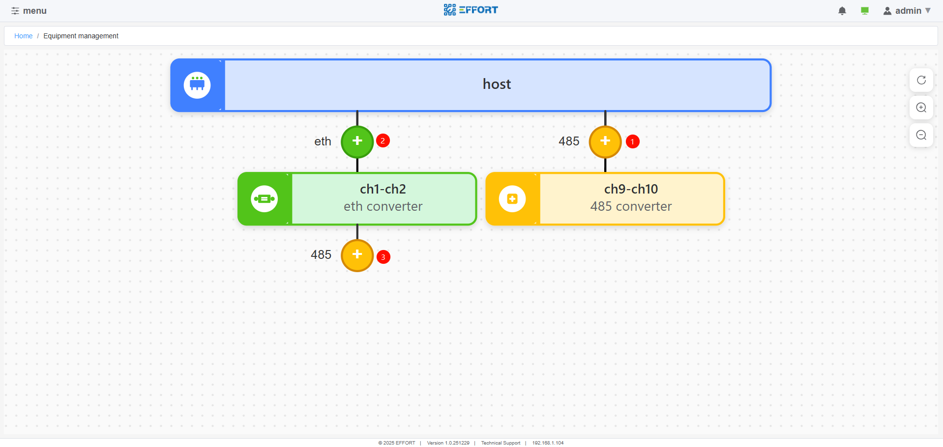
Equipment management
①Add the sub converter connected to the host 485 bus to the system
②Add the master converter, which is on the same network segment as the host, to the system
③Add the sub converter connected to the master converter via the 485 bus to the system
2.2.3.1 Add sub converter
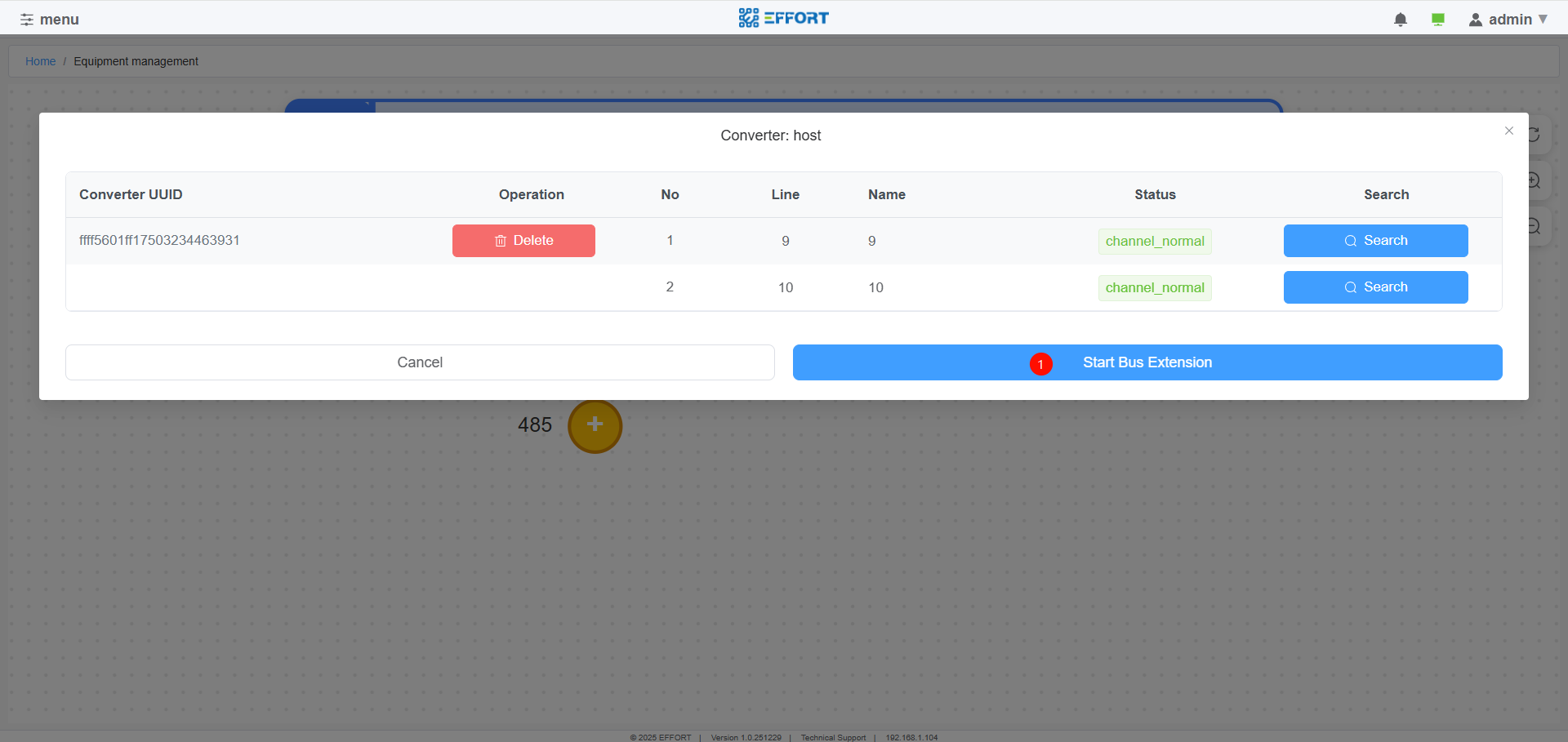
Bus Expansion
①start bus expansion
- Start scanning the sub converters on the 485 bus to expand the bus
2.2.3.2 Add the master converter
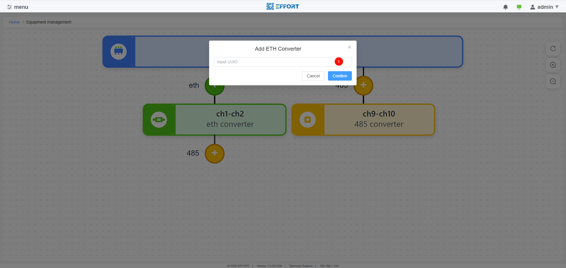
Net Converter Add
- ①Enter the UUID of the master converter to add it
2.2.3.3 Host operation
Clicking the host's icon allows you to perform the following operations on the host:
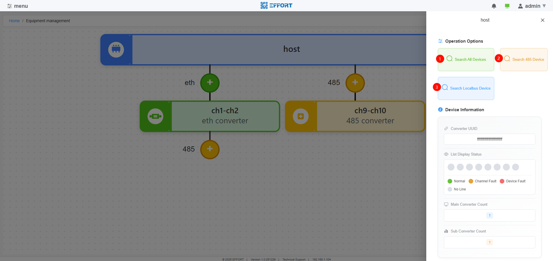
Host Operation
- ①Start device search for all DALI channels in the system
- ②Start device search for all DALI channels of sub converters connected to the host 485 bus
- ③Start device search for the host's own DALI channel (not supported yet)
2.2.3.4 Master converter operation
Clicking the master converter's icon allows you to perform the following operations on the master converter:
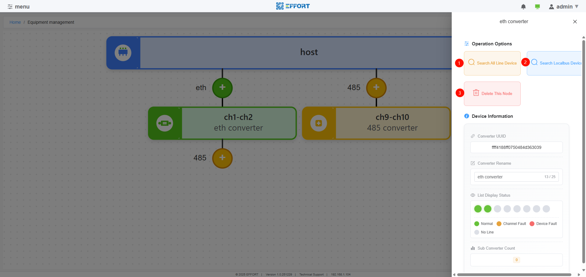
Master Converter Operation
- ①Start device search for the DALI channels of the master converter itself, as well as the DALI channels of the sub converters attached to the master converter via the 485 bus
- ②Start device search for this master converter's own DALI channel
- ③Delete this master converter from the system
2.2.3.5 子转换器操作
Clicking the sub converter's icon allows you to perform the following operations on the sub converter:

Sub Converter Operation
- ①Start device search for this sub converter's own DALI channel
- ②Delete this sub converter from the system
2.2.3.4 Device add
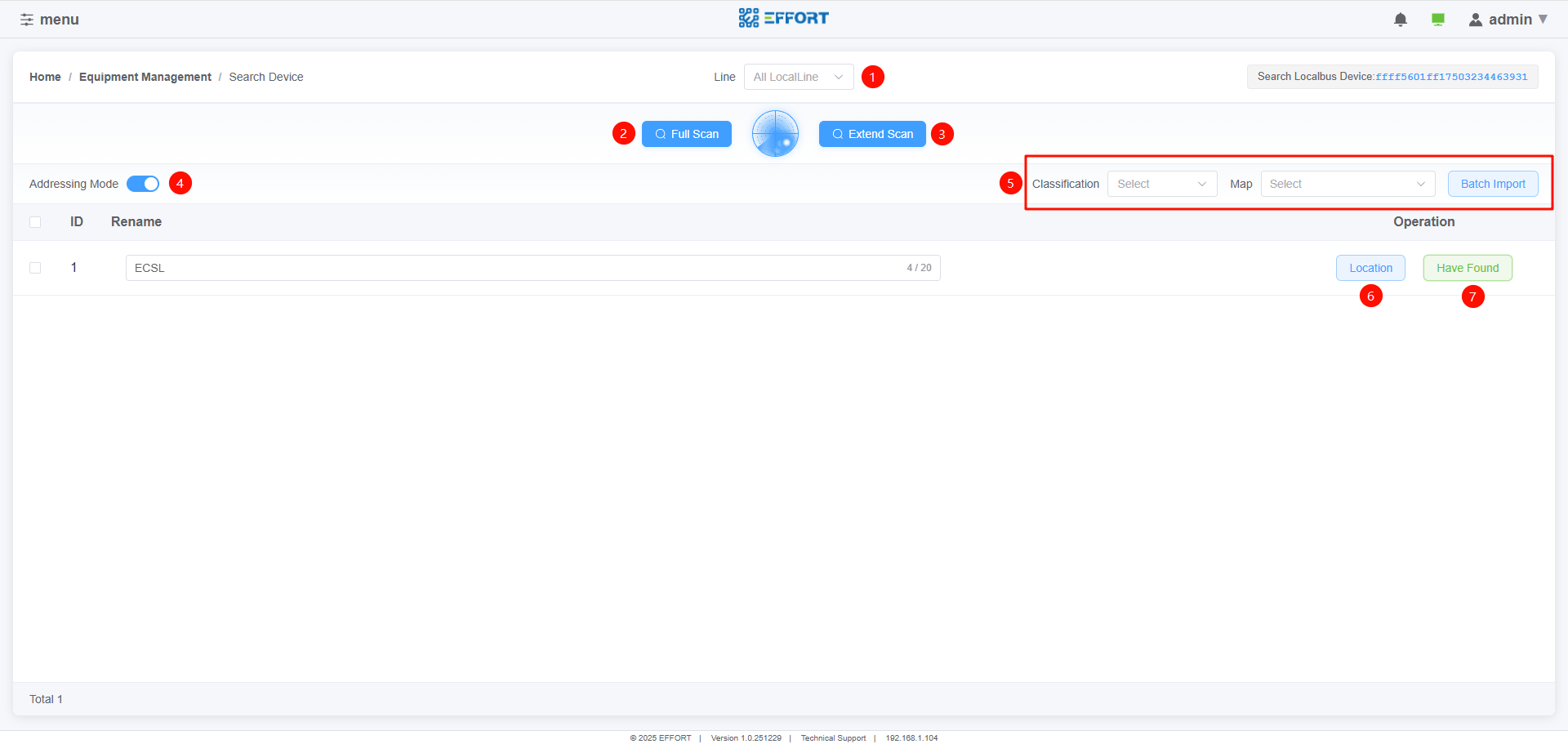
Device add
①Bus selection
- Select the bus number of the device to be scanned
②Full scan
:warning:Delete all short addresses of devices on the bus, and then scan the devices
Suitable for installation in new projects
③Extend scan
Do not change the short addresses of existing devices, and allocate addresses to newly added devices.
Suitable for adding or replacing equipment to already installed projects
④Loop location function
Perform cyclic location on the devices that have been found
After enabling this feature, the device being located will display the "⑦Have Found" button. At the same time, the device is flashing to help the installer locate it.
When the device is found and the "⑦Have Found" button is clicked, it will automatically switch to the next device.
⑤Import function
- Import devices in batches or individually into the map, and set device types.
⑥Location function
- Enable the locate function of a single device
⑦Have Found
- Use in the 'Loop Location Function'
2.3 Device
2.3.1 Device page
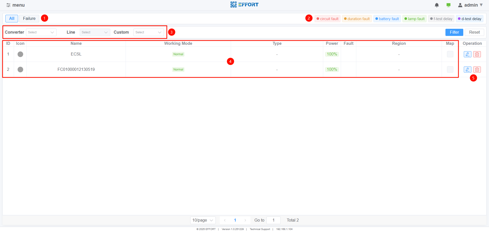
Device
①View Mode
All:show all devices
Failure:Only display fault devices
②Fault icon definition
③Display filter
④Device brief information
⑤Device details or delete
2.4 Command
2.4.1 Command page
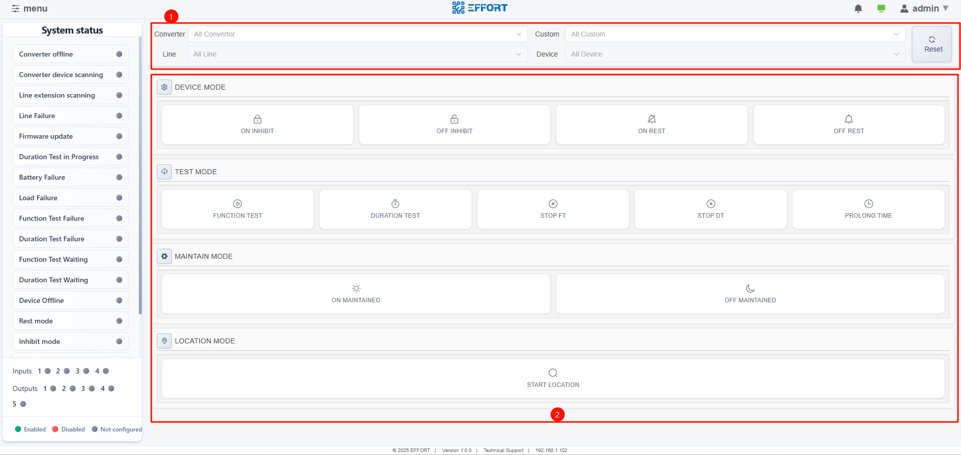
Command page
①Device filtering for sending command
②Command type
- Click the button to send command
2.5 Configuration
The supported configuration items include:
2.5.1 General
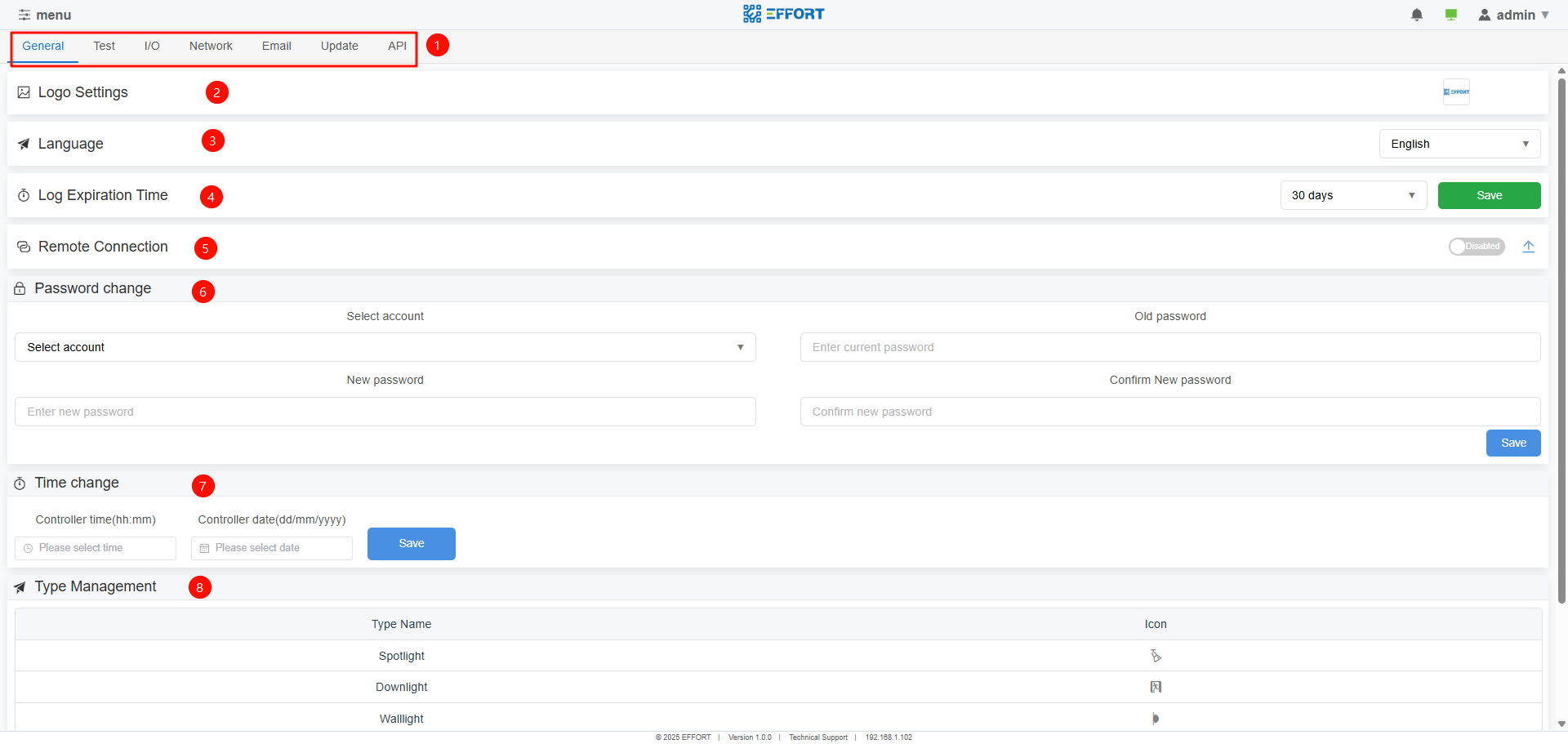
General
①Configuration List
②Logo settings
③Language
④Log expiration time
- Automatic cleaning time of system logs
⑤Remote connection
Enable this function to access the host through the Internet
For detailed operation methods, please refer to “B.remote control instructions”
⑥Password change
⑦Time change
Local host time
When using it for the first time, the time needs to be changed to the time of the installation project area
Built in button cell in the host
⑧Type management
- Custom device type
2.5.2 Test
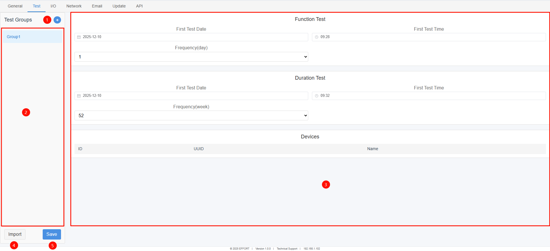
Test
①Add Test Group
②Test group list
③Test group configuration details
④Import
- Import devices for the testing group
⑤Save
- save the test group configuration and send the device testing time information
:warning:Before clicking Save, the test information will not take effect and will not be sent to the device
2.5.3 IO
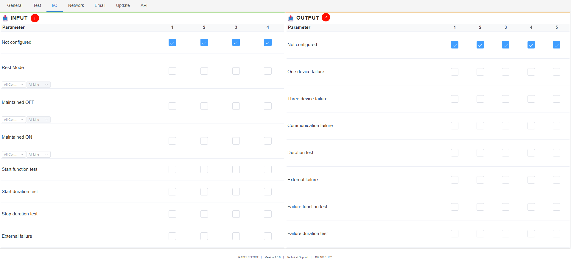
IO
①INPUT
- The action executed after selecting a valid host output port
②OUTPUT
- Configure trigger events for output ports
2.5.4 Network
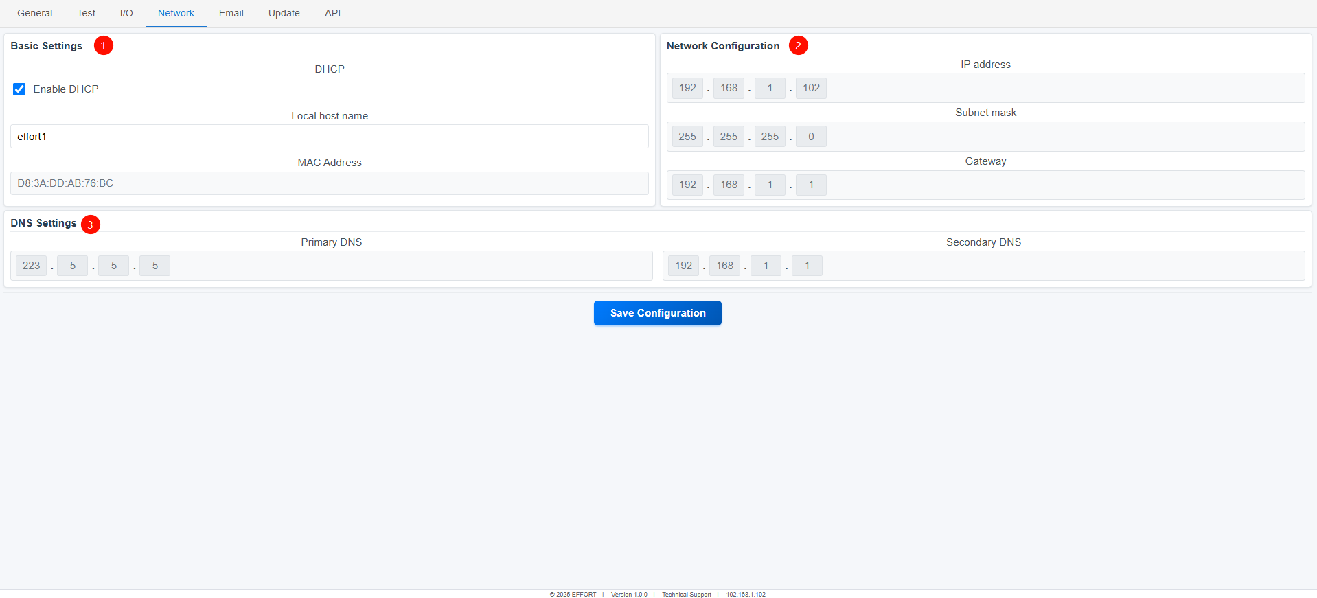
Network
①Basic settings
DHCP(Dynamic Host Configuration Protocol)
Host name
②Network configuration
- When configured as DHCP, network information is automatically obtained
③DHS settings
- When configured as DHCP, DNS information is automatically obtained
:warning:Click save to enable configuration
2.5.5 Email
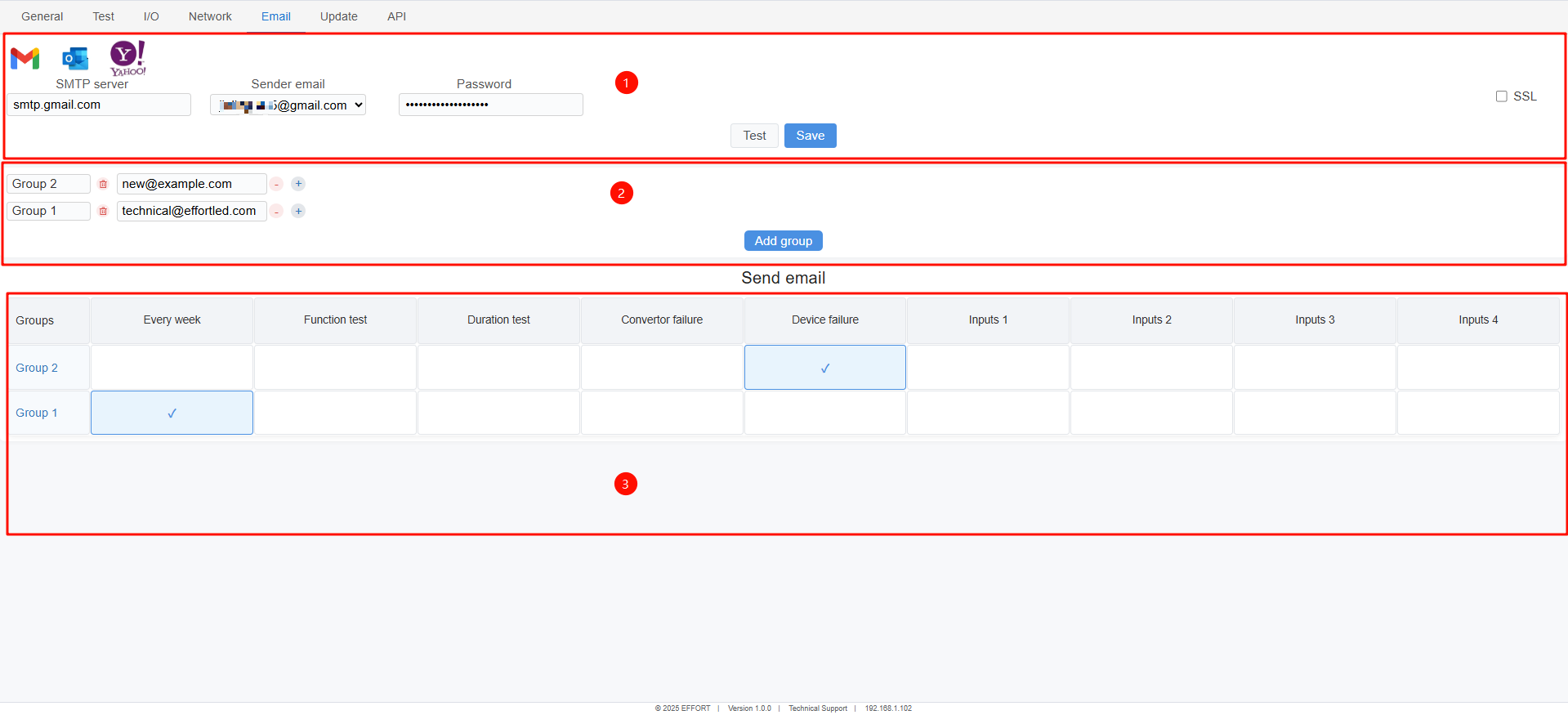
①email account
After the event is triggered, information will be sent to the members of the receiving group using this email account.
SMTP Server:The SMTP server address of the selected sender email
Support quick input of SMTP server addresses for Google,Outlook and Yahoo.
Other email addresses can also be supported, as long as the email server is based on the SMTP protocol
Click Test to test if the input email information is correct
Click the Test button to send a test email to all members in the email receiving group to verify if there are any errors in the email information.
:warning:Can be used only when the host is connected to the Internet
②Email receiving group
③Set the information that the receiving email needs to receive.
2.5.6 Update
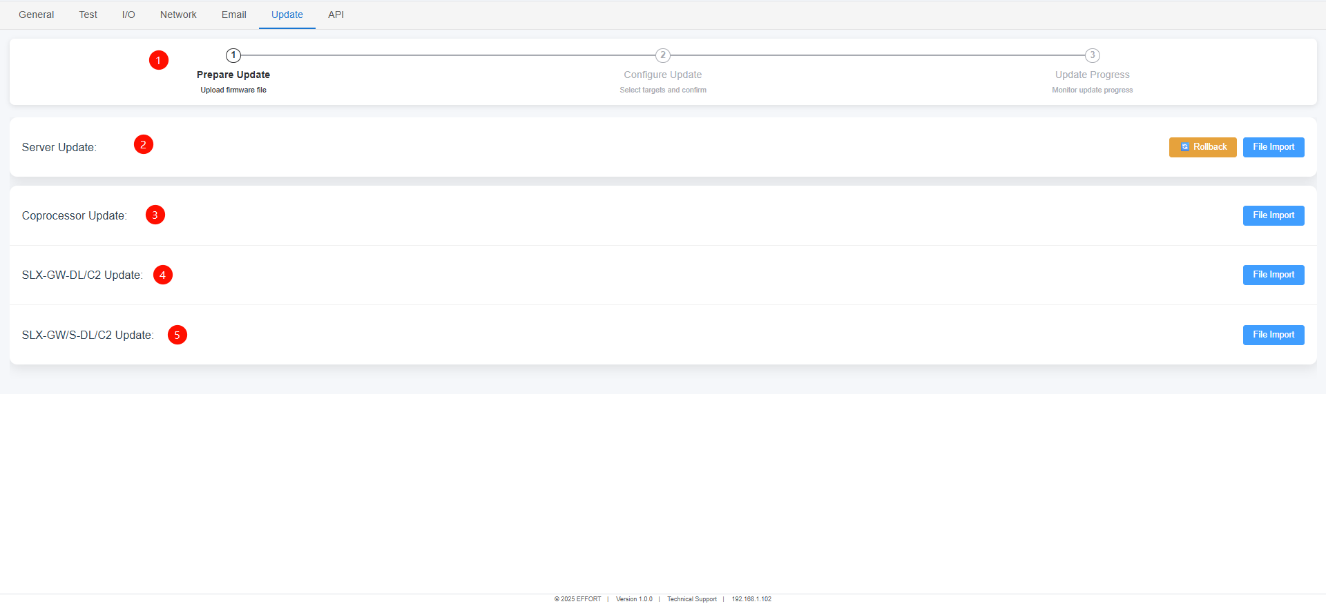
Update
①Update progress
②Update the host web service program
③Update the program of the host's internal co processor
④Update the program of the master converter in the system
⑤Update the program of the sub converter within the system
:warning:If the file is selected incorrectly, it cannot be updated.
2.5.7 API
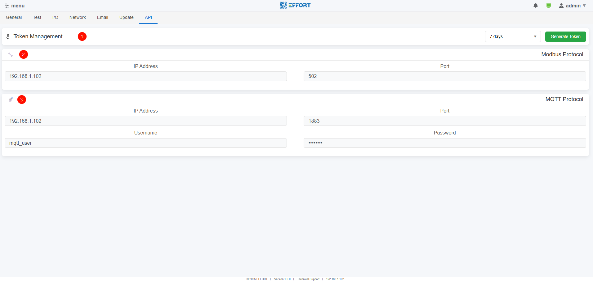
API
①Token generation and refresh for API connection
②Modbus protocol
③MQTT protocol
2.6 Logbook
2.6.1 Logbook page
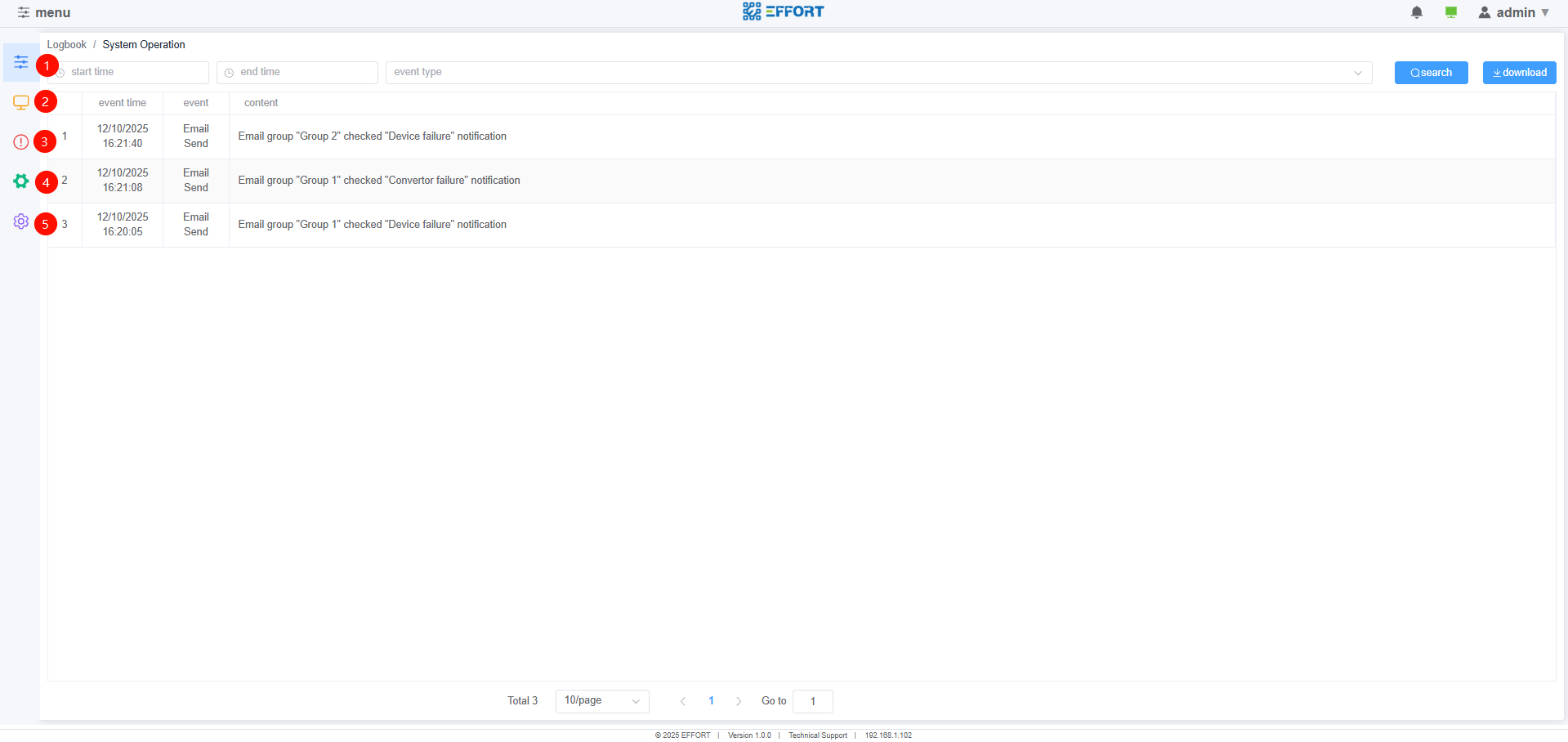
Logbook page
①System operation log
②Test record log
③Equipment failure log
④Equipment addition and deletion operation log
⑤Command log
2.7 Map
2.7.1 Map page
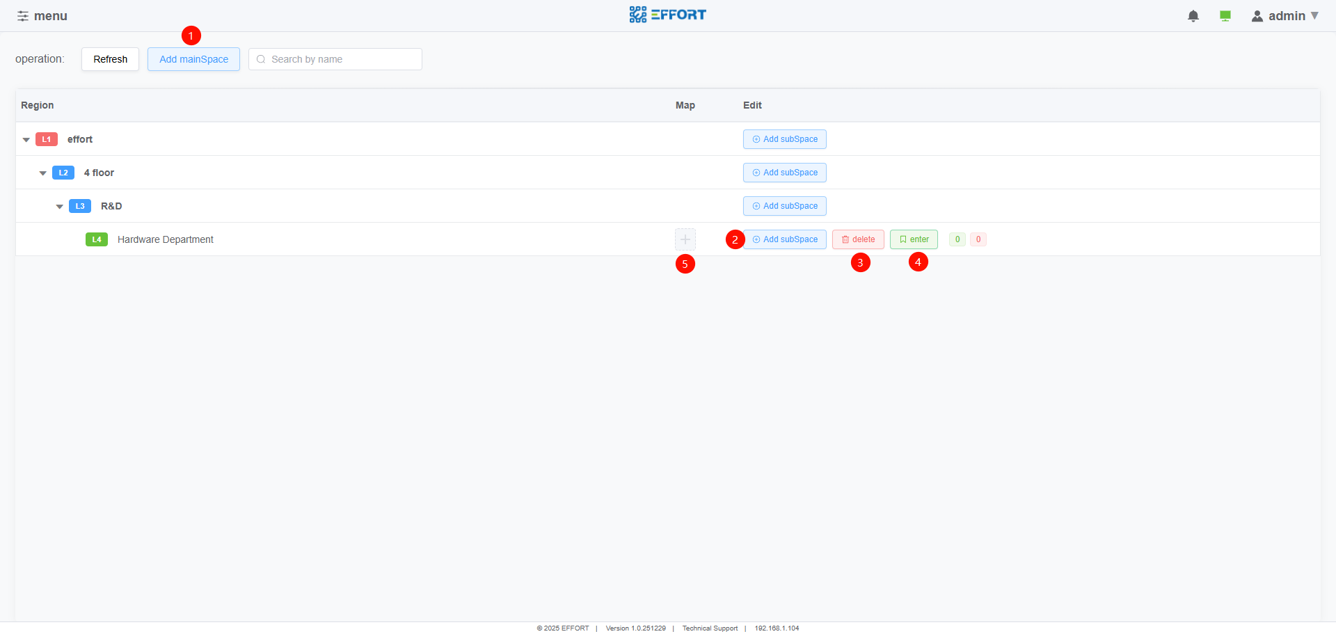
Map page
①Add main space
②Add subspaces to the main space
③Delete space
④Entering the space
⑤Import map for space
2.7.2 Map detail
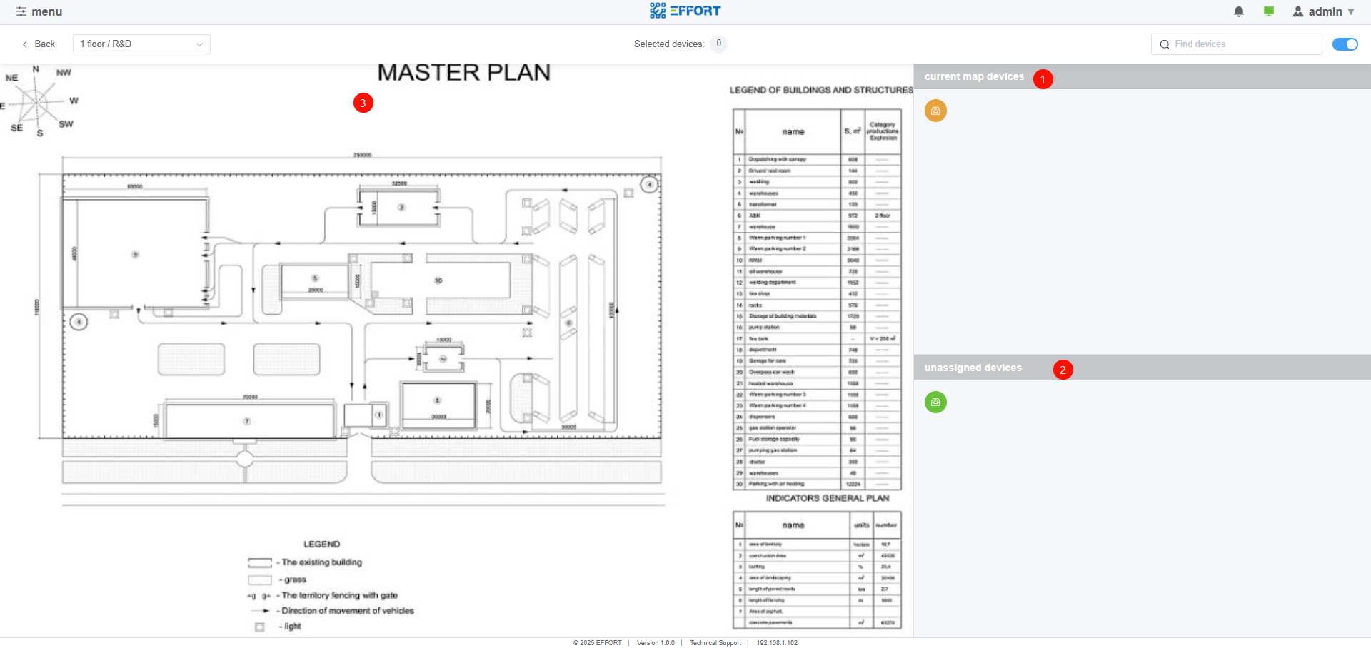
Map detail
①Devices set as this area
②Devices without assigned areas
③Map display page
- Devices ① and ② can be dragged into the map
2.8 Host Connect
2.8.1 Host Connect page
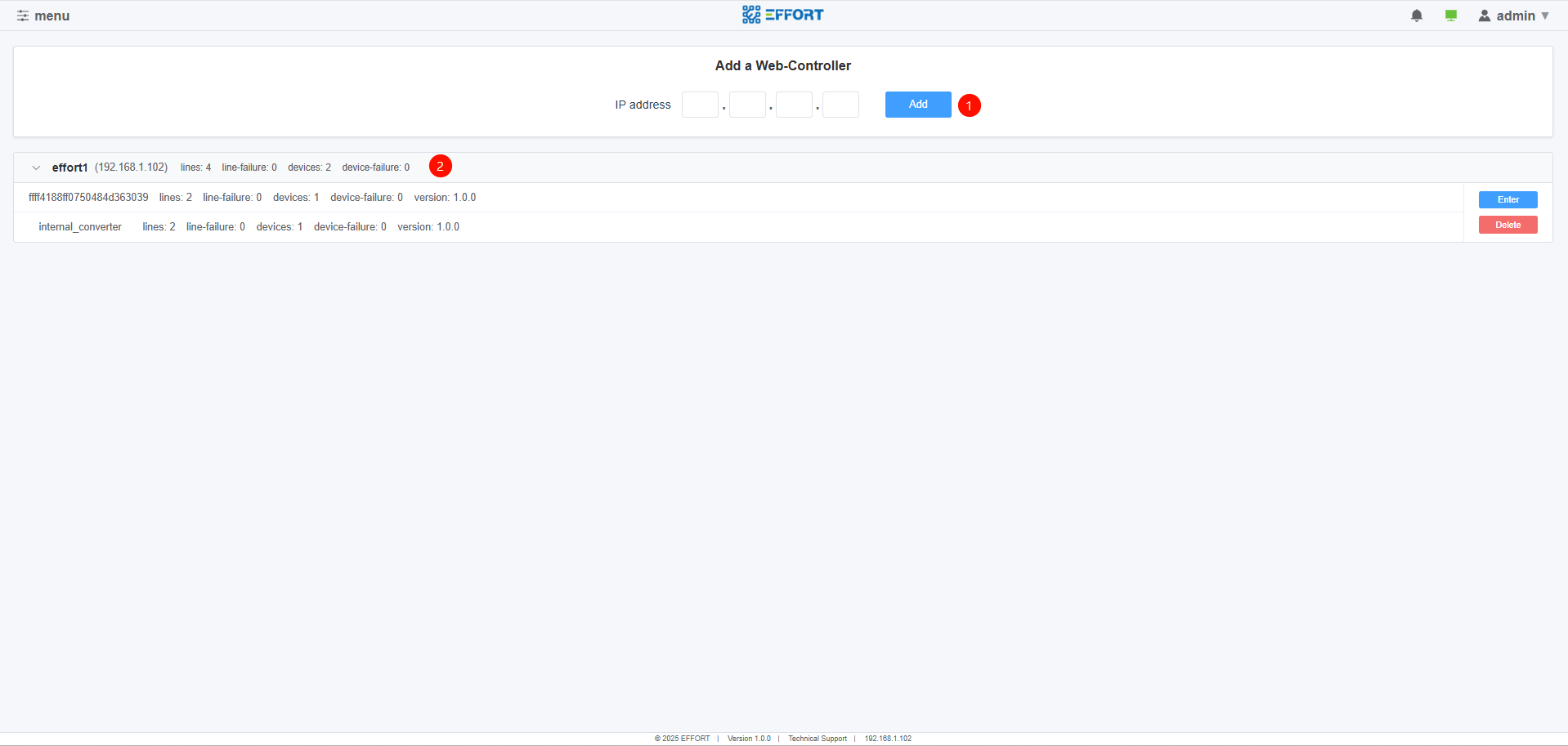
Host Connect page
Add other hosts through IP address
Overview information of added hosts
- Click enter to jump to the detailed page of the corresponding host
3.System administration
3.1Account and Permissions
SafeLUX offers two types of accounts, administrator and guest.
| Page/Function | Administrator | Guest |
|---|---|---|
| Page:Home | Support | Support |
| Page:Device | Support | Support |
| Page:Command | Support | Support |
| Page:Configuration | Support | Not |
| Page:Logbook | Support | Support |
| Page:Layout | Support | Support |
| Page:HostConnect | Support | Support |
| Function:Equipment add and delet | Support | Not |
| Function:Host add and delet | Support | Not |
4.Troubleshooting
To be supported
5.Appendix
5.1 FAQ
To be supported
5.2 Technical support email
To be supported
No comments to display
No comments to display