
5.hardware installation manual
Hardware installation manual
This document is the hardware installation manual for the SafeLUX system
Adapted system version:V1.0.0
Document version:V1.0
Release Date:December 10, 2025
Publisher:EFFORT
Document modification record
| Version | Date | Modified content | Modifier |
|---|---|---|---|
| V1.0 | 20251210 | First creat | Mihcael |
1.Document overview
1.1 Overview
This document is the hardware installation manual for the SafeLUX system, covering the hardware installation methods of the system's core components (host, master converter, sub converter, device) as well as other necessary accessories such as AC-DC adapters, display screens, routers, and switches.
By reading this document, you can quickly learn about various hardware installation methods of the system.
1.2 Target readers
- Hardware Installation Engineer
1.3 Scope of Document Content
System Topology Diagram
Hardware Connection Step-by-Step Instructions
1.4 Associated Documents
“3.1 SLX-HT datasheet”
“3.2 SLX-GW-DL_C2 datasheet”
“3.3 SLX-GW_S-DL_C2 datasheet”
“3.4 SLX-CR datasheet”
“4.1 SLX-HT user manual”
“4.2 SLX-GW-DL_C2 user manual”
“4.3 SLX-GW_S-DL_C2 user manual”
“4.4 SLX-CR user manual”
1.5 Safety Instructions
:warning: Operating Temperature Range: -20°C to 55°C. Do not use the device outside this temperature range.
:warning: Avoid direct sunlight exposure to prevent housing deformation and internal component damage.
:warning: Keep the device clean and free of dust accumulation to avoid poor heat dissipation.
:warning: Use only power supply units that meet the specified requirements.
:warning: Installation must be performed by professional personnel. Installation by non-professionals may cause equipment damage or personal injury.
:warning: Do not use the device in humid, dusty, or corrosive environments.
:warning: Ensure the installation location is away from heat sources and flammable materials.
:warning: A reset operation will clear all connected devices. Perform this operation only when necessary and by professional personnel.
:warning: Implement electrostatic discharge (ESD) protection during installation.
1.6 Term
Host
- SLX-HT
Master converter
Gateway devices with network communication
eg.SLX-GW-DL/C2
Sub converter
Gateway device with 485 communication
eg.SLX-GW/S-DL/C2
Node
- Emergency lighting fixtures or emergency drivers
Equipment
- Include “Main converter” “Sub converter” “Node”
2.System Topology Diagram
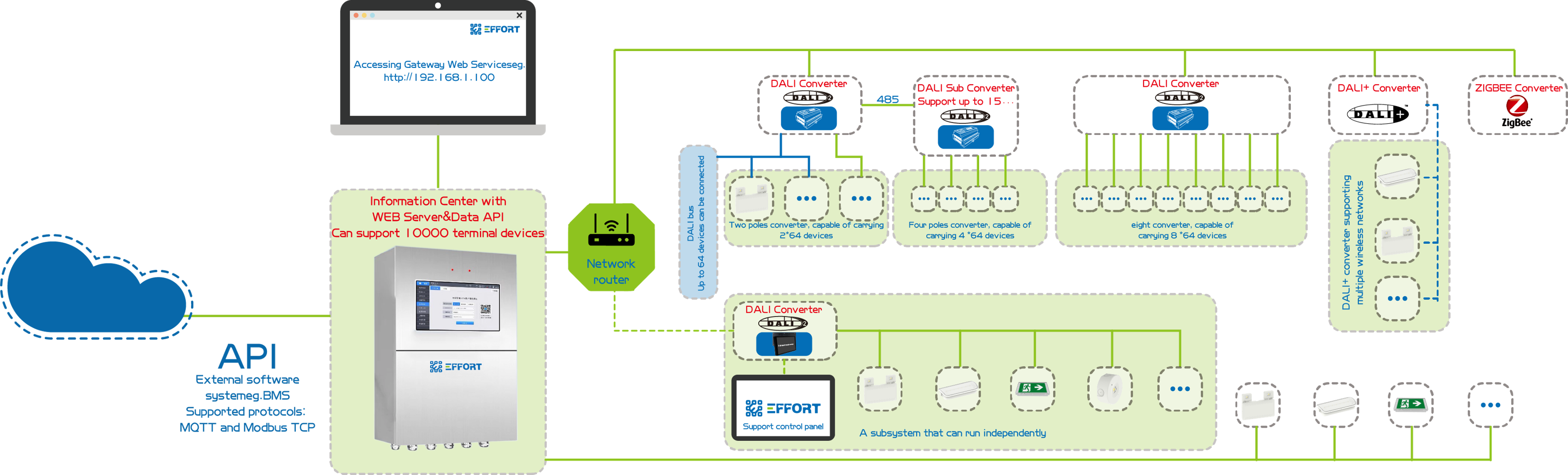
system topology diagram
The SafeLUX system consists of various components. The core components include SLX-HT, SLX-GW-DL/C2, SLX-GW/S-DL/C2, and various types of lamps.
SLX-HT is the central control host of the entire system, SLX-GW-DL/C2 is a DALI master converter with network communication, and SLX-GW/S-DL/C2 is a DALI sub converter with RS485 communication.
SLX-HT is equipped with network and RS485 interfaces. It can connect to the SLX-GW-DL/C2 DALI master converter via the network interface, or to the SLX-GW/S-DL/C2 DALI sub converter via the RS485 bus. Lamps are connected to their respective converters.
SLX-CR is a cabinet-type central control unit, which internally consists of SLX-HT, a configurable number of SLX-GW/S-DL/C2, a touch screen, as well as necessary ACB , RCD and AC-DC power supplies.
2.1 Core Components List
| Component Name | Function Description | Datasheet Link | User Manual Link |
|---|---|---|---|
| SLX-HT | Host | 3.1 SLX-HT datasheet | 4.1 SLX-HT user manual |
| SLX-GW-DL_C2 | Master converter with 2 channel | 3.2 SLX-GW-DL_C2 datasheet | 4.2 SLX-GW-DL_C2 user manual |
| SLX-GW_S-DL_C2 | Sub converter with 2 channel | 3.3 SLX-GW_S-DL_C2 datasheet | 4.3 SLX-GW_S-DL_C2 user manual |
| SLX-CR | cabinet-type central control unit(host with sub converter) | 3.4 SLX-CR datasheet | 4.4 SLX-CR user manual |
3.Hardware Connection Step-by-Step Instructions
3.1 Host Installation (SLX-HT or SLX-CR)
Refer to 4.1 SLX-HT user manual -> 4. Installation Guide.
or
Refer to 4.4 SLX-CR user manual -> 4. Installation Guide.
:warning:No power-on required
3.2 Master Converter Installation(If there is a connection requirement)
Refer to 4.2 SLX-GW01-DL/C2 user manual -> 4. Installation Guide.
:warning:No power-on required
3.3 Sub Converter Installation(If there is a connection requirement)
Refer to 4.3 SLX-GW_S-DL_C2 user manual -> 4. Installation Guide.
:warning:No power-on required
3.4 Lamp Installation
Refer to the lamp's installation manual.
:warning:No power-on required
3.5 Power On
Power on all devices.
3.6 Master Converter Check
Check if each indicator light shows green. If any red light is flashing, refer to the user manual for troubleshooting and problem localization.
:warning:Focus on checking the status of the power indicator and network indicator.
Click the function button to check if the indicator lights of all connected DALI lamps flash and change. If there is no change, it indicates that the DALI wiring of the corresponding lamps is not properly connected.
If there are sub converters under the RS485 bus, while performing Step 2, also check whether the indicator light status of the DALI lamps connected to the sub converters will flash and change.
3.7 Sub Converter Check
Check if each indicator light shows green. If any red light is flashing, refer to the user manual for troubleshooting and problem localization.
:warning:Focus on checking whether the network status is abnormal. (Since the host requires a certain amount of time to start up, please check 2 minutes after power-on to verify whether the network connection between the master converter and the host is correct.)
Click the function button to check if the indicator lights of all connected DALI lamps flash and change. If there is no change, it indicates that the DALI wiring of the corresponding lamps is not properly connected.
3.8 Host Check
Check the power indicator light.
If a display is connected, check whether it displays normally. If a touch display is connected, verify whether the touch function works properly.
If a network cable is connected, after logging into the system, check whether the IP address displayed at the bottom of the home page is correctly assigned.
If there are sub converters under the RS485 bus, while performing Step 2, also check whether the indicator light status of the DALI lamps connected to the sub converters will flash and change.
3.9 Log in to the system for in-depth usage.
Refer to 6.software operation user manual
4. Troubleshooting
4.1 Common Issues Troubleshooting
4.2 Common Questions Q&A
5. Technical Support and Maintenance
Technical support email:technical@effortled.com
Daily maintenance cycle (clean the dust from the gateway's heat dissipation holes every 3 months; check if the wiring terminals are loose every 6 months);
Firmware upgrade method (Host WEB page -> Configuration -> Update -> Upload firmware);
No comments to display
No comments to display