
4.2 SLX-GW-DL_C2 user manual
SLX-GW01-DL/C2 User Manual
This document is the user manual for the master converte SLX-GW01-DL/C2 in the SafeLUX system
Document version:V1.0
Release Date:December 15, 2025
Publisher:EFFORT
Document Modification Record
| Version | Date | Modified content | Modifier |
|---|---|---|---|
| V1.0 | 20251215 | First creat | Mihcael |
1. Safety Instructions
:warning: Operating Temperature Range: -20°C to 55°C. Do not use the device outside this temperature range.
:warning: Avoid direct sunlight exposure to prevent housing deformation and internal component damage.
:warning: Keep the device clean and free of dust accumulation to avoid poor heat dissipation.
:warning: Use only power supply units that meet the specified requirements.
:warning: Installation must be performed by professional personnel. Installation by non-professionals may cause equipment damage or personal injury.
:warning: Do not use the device in humid, dusty, or corrosive environments.
:warning: Ensure the installation location is away from heat sources and flammable materials.
:warning: A reset operation will clear all connected devices. Perform this operation only when necessary and by professional personnel.
:warning: Implement electrostatic discharge (ESD) protection during installation.
2. Product Overview
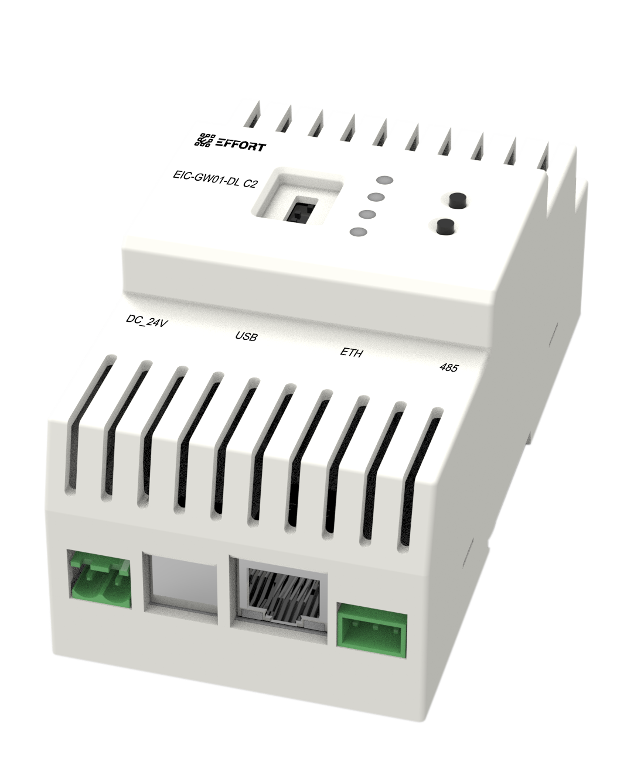
SLX-GW-DL_C2
Used to convert DALI signals into network signals and transmit them to the host through Ethernet cables
Master converter for DALI DT1 device control
Local web pages can configure network parameters
RS485 port expansion DALI bus
100M Ethernet communication
24V DC power supply
DALI channel number:2
Rail mounted installation
Model Description:
SLX:SafeLUX
GW:master converter(gatway)
DL:DALI
C2:Channel*2
Interface Definition and Layout Diagram of Indicator Lights and Buttons:
interface
| Interface No. | Interface Name | Terminal Type | Wiring Sequence Definition | Wiring Notes |
|---|---|---|---|---|
| 1 | Power Interface | 2-pin Plug-in Terminal Block (0.2-1.5mm²) | 1=DC+(24V)、2=DC-(GND) | Do not connect to AC power. |
| 2 | USB Slave Interface | USB-B | - | - |
| 3 | RJ45 Ethernet Port | RJ45 | Complies with T568B wiring | Use Cat5e or above shielded network cable, maximum length ≤ 100m. |
| 4 | RS485 Interface | 3-pin Plug-in Terminal Block (0.2-1.5mm²) | 1=GND、2=A、3=B | A/B wires must not be reversed; add 120Ω terminal resistors at both ends of the bus. |
| 5 | DALI Interface * 2 | 2-pin Screw-Type Terminal Block (0.5 - 2.5mm²) | 1=DALI+、2=DALI- | Two channels adopt independent wiring; do not mix the connections. |
| 6 | Network segment address encoders | 0-9 encoded digital encoder | - | - |
| 7 | System Indicator Light | - | - | - |
| 8 | System Indicator Light | - | - | - |
| 9 | System Indicator Light | - | - | - |
| 10 | Power Indicator Light | - | - | - |
| 11 | System Button | - | - | - |
| 12 | Function Button | - | - | - |
3. Mechanical Dimensions & Packaging Specifications

SLX-GW-DL_C2_size
unit:mm
Weight per pc:
Packaging dimensions:
Packing list:
4. Installation Guide
4.1 Unboxing Inspection
Check the package contents: SLX-GW-DL_C2, installation accessories, and other necessary components.
Inspect the product appearance for damage.
4.2 Installation Environment Requirements
Ambient Temperature: -20℃ to 55℃.
Ambient Humidity: 10% ~ 90% RH (no condensation; do not install in humid environments such as flooded areas of basements).
Installation Location: Keep away from heat sources, avoid direct sunlight, and stay clear of strong electromagnetic interference sources (e.g., frequency converters, high-power motors, high-voltage cables) with a minimum distance of ≥ 1 meter.
Installation Method: Only supports 35mm standard DIN rail mounting.
Rail Thickness: 1.0 ~ 1.5mm; the bayonet must be securely fastened during installation.
The length of the RS-485 bus shall not exceed 800 meters.
Network Environment: The host network level should be greater than or equal to the master converter's network level. It is recommended that the host and converter be at the same network level. A local area network (LAN) with DHCP assignment capability is advised.
4.3 Power Supply and Cable Adaptation Requirements
4.3.1 Power Supply Adaptation Requirements
SLX-HT must use a DC 24V power supply that meets the following parameters:
- Output Voltage: DC 24V (allowable range: 22.8V - 25.2V);
- Rated Power: ≥2W (to avoid device restart due to insufficient power supply);
- Power Supply Type: AC/DC adapter or switching power supply complying with safety standards;
- Interface Matching: Must be used with 2-pin plug-in terminal blocks (pin spacing 5.08mm). Gold-plated terminals are recommended to reduce contact resistance.
4.3.2 Cable Selection Requirements
Cables for different interfaces shall be selected in accordance with the following specifications to avoid signal interference or transmission failures:
| Interface Type | Cable Specification Requirements | Maximum Transmission Distance | Additional Requirements |
|---|---|---|---|
| RJ45 Ethernet Port | Cat5e or higher shielded network cable (CAT5e SF/UTP) | ≤100 meters | Waterproof cables shall be used for outdoor wiring |
| RS485 Interface | Twisted pair shielded cable (RVSP 2×0.75mm²) | ≤1200 meters | The shield layer shall be single-ended grounded (ground resistance ≤4Ω) |
| DALI | 1.50 mm^2 Conventional Cables | ≤300 meters | Do not use Ring wiring or Mesh wiring. |
| USB | Standard copper cable (AWG28-24 gauge) | ≤5 meters | The cable shall include four cores: D+, D-, VCC and GND; Shielded cables shall be used for lengths exceeding 3 meters |
Note: For detailed technical parameters (such as power supply parameters, RS485 technical parameters, etc.), refer to the 《SLX-GW-DL_C2 datasheet》.
4.4 Installation Steps and Wiring Instructions
Select the installation location: ensure compliance with environmental requirements.
Mount the master converter on the guide rail.

install
Connect the master converter to the network router or the switch under the router via a network cable.

net_connect
Connect to the sub converter via a 485 cable. (If it is necessary to connect to the sub-converter via 485)

485_connect
If the master converter and the host are in the same LAN segment, you can set the network segment address encoders of the master converter and the host to the same value to enable the network automatic pairing function. A.quick pairing instructions for master converters

address_switch
Connect the DALI cable to the DALI lamps.
Connect the output interface of the power supply to the master converter's power supply port.
power_connect
Power on
Log in to the host WEB system to operate the converter
5. Operation Instructions
5.1 Key Functions
| Key | Action | Description |
|---|---|---|
| system | Long Press | Reset |
| system | Double Press | Reboot |
| function | Single Press | All devices under all DALI channels execute the Identify command |
| function | Long Press | Extended Scan for All DALI Channel Devices |
| function | Double Press | 485 bus scanning sub converter |
| system+function | Long Press | Reset DALI Devices under All DALI Channels |
5.2 Indicator Light Status
| Indicator | Status | Description |
|---|---|---|
| system | Green light solid on | Working normally, no data interaction on 485 bus |
| system | Green light turns off for 100ms once | Working normally, data interaction on 485 bus |
| system | Green light off for 100ms, on for 500ms | System key long press activated |
| system | Green light off for 500ms, on for 500ms | 485 bus searching for sub converters |
| system | Red light off for 100ms, on for 900ms | IP not assigned or network cable disconnected |
| system | Red light off for 250ms, on for 250ms | Sub converter communication abnormality |
| system | Red light off for 500ms, on for 500ms | Host server not connected |
| cahnnel X | Green light solid on | Working normally, no data interaction on DALI bus |
| cahnnel X | Green light turns off for 100ms once | Working normally, data interaction on DALI bus |
| cahnnel X | Green light off for 100ms, on for400ms | Function key long press activated |
| cahnnel X | Green light off for 500ms, on for 500ms | DALI bus X searching for device |
| cahnnel X | Green light off for 1000ms, on for 1000ms | Device duration test in Progress on DALI Channel X |
| cahnnel X | Red light solid on | DALI Channel X fault |
| cahnnel X | Red light off for 250ms, on for 250ms | Device fault on DALI Channel X |
| cahnnel X | Red light off for 500ms, on for 500ms | Device miss on DALI Channel X |
5.3 Network Instructions
5.3.1 Description of master converter Network IP and Parameter Settings
The master converter supports two methods for network IP and parameter settings:
DHCP for network IP and parameter assignment
Static settings for network IP and parameter configuration
DHCP is the default method for master converter network IP and parameter settings.
If you need to modify the host's network IP and parameters, refer to 5.4Master converter Network Parameter Configuration.
DHCP automatically assigns network IP and configuration parameters to the host via a router. It requires no manual settings from the user and enables quick network access for the device.
Static settings require the user to manually enter parameters such as IP address, subnet mask, network gateway address, and DNS server for network configuration.
:warning: If you are not familiar with network principles and allocation methods, please use the default DHCP method.
5.3.2 Target Network Configuration
The target IP address and target port within the target network configuration refer to the IP address and data port of the host connected to the master converter.
The default target address is 192.168.10.1, and the data port is 1883.
If the master converter and the host are in the same LAN segment, you can set the network segment address encoders of the master converter and the host to the same value to enable the network automatic pairing function. After the successful automatic matching, the target IP address and target port of the master converter will be automatically modified. A.quick pairing instructions for master converters
If the LAN where the host is located is the upper-level LAN of the LAN where the master converter is located, it is necessary to modify the target IP address and target port of the master converter. Otherwise, the master converter will remain in the state of "Host server not connected", and the system indicator light will "Red light off for 500ms, on for 500ms".
- :warning:If the LAN where the host is located is the lower-level LAN of the LAN where the master converter is located, the device will be unable to connect. The network hierarchy of the host must be higher than that of the master converter. How to modify the target IP address and target port: please refer to Section 5.4.Master converter Network Parameter Configuration。
5.4 Master converter Network Parameter Configuration
5.4.1 Find the master converter's IP through the router's management backend.
First, ensure that the converter's system indicator light is not in the state of "red light on for 100ms and off for 900ms"(IP not assigned or network cable disconnected). In this state, the converter is in one of the following states:
Static IP setting with network cable disconnected
DHCP setting with network cable disconnected
DHCP setting with network IP not assigned
In the above cases, the master converter has not been added to the router's network, so the master converter will not be found in the router's management backend.
The master converter's network is set to DHCP (default network setting)
Then log in to the router management background, locate the device with the hostname EIC-GW01-DL_XXXXXX, and record its IP address.

router_management_backend
:warning:The methods for logging in to the management background of different routers vary, and you need to consult the network administrator for the specific method.
Master converter network set to static IP
Directly record its static IP address.
:warning: If you have forgotten the network settings of the master converter, please reset the converter directly to ensure its network setting is set to DHCP.
5.4.2 Accessing the Master converter's Configuration Page via Browser
Ensure the computer and the master converter are on the same local area network (LAN). Open a browser on the computer and enter the master converter's IP address recorded in Section 5.4.1, and the following interface will be displayed in the browser:
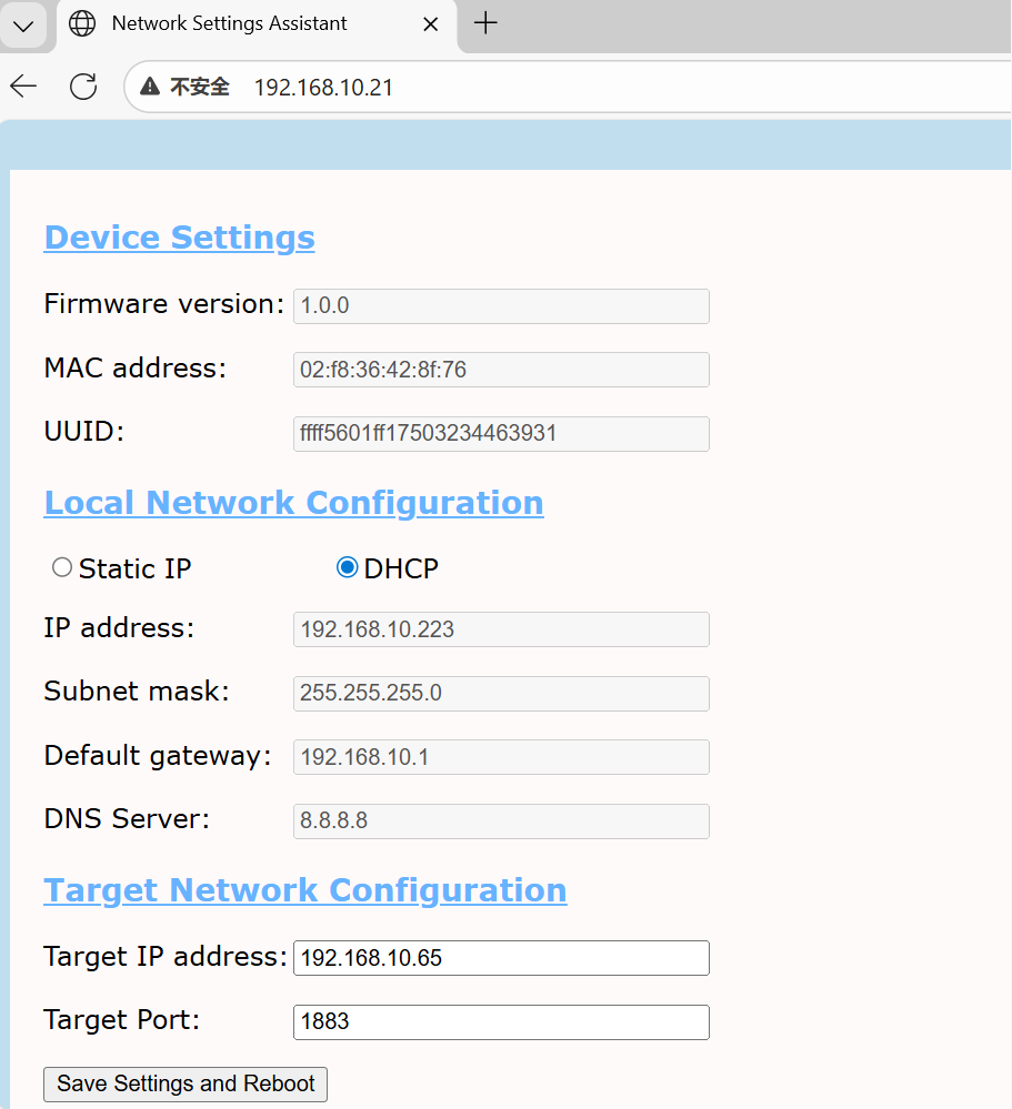
converter_management_backend
Device Settings:Master converter device information
Local Network Configuration:Master converter network settings
Target Network Configuration:The network information of the host that the master converter needs to connect to.(Target IP address and target port)
6. Testing and Verification
This product is a DALI 2-channel master converter component in the SafeLUX system, therefore it needs to be used in conjunction with the SafeLUX system host.
After adding a converter to the SafeLUX system, you can control the converter and the DALI lamps mounted under the converter DALI bus on the SafeLUX system page.
For more information, please refer to the SafeLUX host user manual, SafeLUX system user manual, and other related documents.
Basic Verification Steps:
Hardware connect
Power on the system
Log in to the host system
Access the device management page
Add the master converter (Add master converter via network)(If the host and the master converter are on the same local area network (LAN), automatic converter addition is available)
Perform other operations
7. Troubleshooting
Troubleshooting Based on Indicator Light Status and Description
| Phenomenon | Troubleshooting Directions |
|---|---|
| System indicator light: Red light on for 100ms, off for 900ms | Master converter IP not assigned or network cable disconnected: 1. Check if the network cable is connected. 2. If using the DHCP network allocation method, confirm whether the router supports and has the DHCP function enabled. 3. If using the static IP network allocation method, confirm whether the router's network segment is consistent with the configured static IP network segment. |
| System indicator light: Red light on for 250ms, off for 250ms | Sub converter communication abnormality: 1. Check if the 485 bus connected to the sub converter is properly connected. 2. Check if the sub converter is powered off or abnormal. |
| System indicator light: Red light on for 250ms, off for 250ms | Server not connected: 1. Confirm whether the target IP address and target port are configured correctly. 2. Confirm whether the host is powered on. 3. Confirm that there is a correct network connection between the master converter and the host. |
| cahnnel X led:Red light solid on | DALI X Channel Fault: Check DALI Interface Voltage |
| cahnnel X led:Red light off for 250ms, on for 250ms | There is device failure under the DALI X Channel; check whether there is any devie failure under the channel. |
| cahnnel X led:Red light off for 500ms, on for 500ms | Device loss occurs under the DALI X Channel; check for device loss or bus disconnection under the channel, and perform bus cable repair or device repair. |
7.2 Common Questions Q&A
Q:What if the host IP changes after restart?
A:Set IP binding in the router to associate the gateway MAC with a fixed IP.
8. Technical Support and Maintenance
Technical support email:technical@effortled.com
Daily maintenance cycle (clean the dust from the gateway's heat dissipation holes every 3 months; check if the wiring terminals are loose every 6 months);
Firmware upgrade method (Host WEB page -> Configuration -> Update -> Upload firmware);
No comments to display
No comments to display